![]()
|
Bob's Shop Notes: |
Bend a little brass |
|
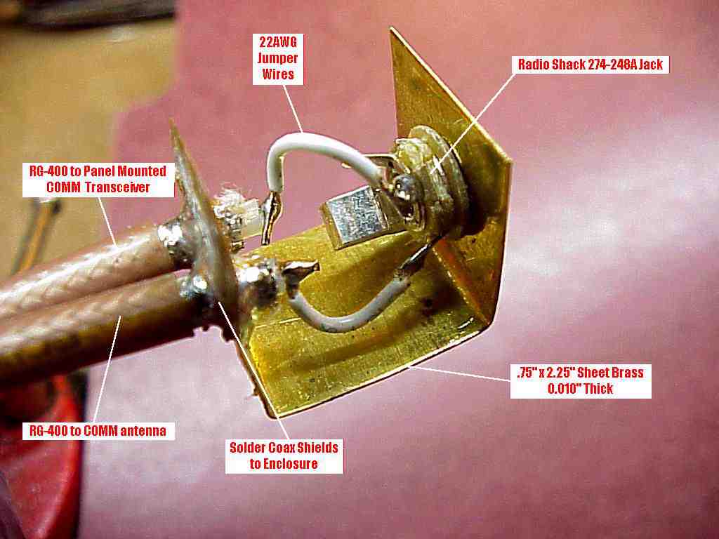
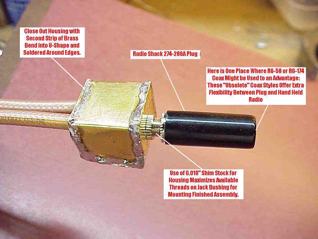
Close it up . . .When you get all done, you'll have a 3/4" hollow cube of brass that houses a miniature, closed circuit headset jack with enough threads left on its mounting bushing to come through a 0.62" panel or bracket and accept the jack's mounting nut. The thin stock is a little flimsy to work with but once the cube is all closed up, it becomes quite rigid. Since the coupler mounts by a single threaded fastener (the bushing of the phone jack) you'll want to support the two feedlines a short distance behind the coupler when it's mounted so that the wire weight will neither flex nor twist the coupler's housing. You can do the same thing with a larger, 1/4" phone jack and make the enclosure a bit larger.
I prefer this technique for several reasons. It's inexpensive. It's compact. It minimizes the number of connectors in your radio's antenna feedline . . . and last, it's easy to do. I'm pretty much down on older coax products like RG-58 (and the miniature cousin RG-174) for use in the airframe wiring, they use polyethylene and polyvinyl chloride plastics. HOWEVER . . . to minimize stress on your hand held's antenna connector -AND- to make handling of the radio easier in the cockpit, these legacy materials are more user friendly than RG-400. Consider fabricating your hand-held-to-coupler jumper from either of these cables. I use RG-400 with my hand held and to make it more cockpit friendly, I use a pair of right-angle BNC adapters to turn the hand-held's antenna routing so that it runs down along the back side of the radio. This makes the relatively stiff RG-400 lay nicely along the radio's "spine" and exit out the bottom - much nicer to use than to have a large loop of coax waving around in the air above the radio. The same technique could be applied to the short coax jumper used with this coupler. One could use a right-angle BNC cable-male on the jumper and you would then need only one BNC right angle adapter . . . this would eliminate one set of joints in the feedline. Fly comfortably . . . 'lectric Bob . . . |
|
 Click here to contact Bob at AeroElectric Connection Click here to contact Bob at AeroElectric Connection |